If you’ve ever stood in a power distribution room or browsed the specs of an electronic energy meter while sourcing for your commercial or industrial site, you’ve probably wondered how these unassuming devices don’t just count the electricity that powers your lights and machines, but also measure something called reactive power. As someone who’s spent the last decade building and perfecting electronic energy meters for small businesses, manufacturing plants, and residential complexes, I get it—reactive power sounds like a niche, jargon-heavy term, but it’s the backbone of a functional, efficient electrical grid. Let me break this down the way I do when I’m walking a new customer through our product catalog, no fancy textbook fluff, just the real, working science that goes into every meter we ship. Electronic Energy Meter

First, let’s ground this in what electricity actually does when it flows through your walls. You have two types of power, not just the “real” power you use to run a drill or heat your office, which does actual work—turns metal, warms air, lights a bulb. Then there’s reactive power, the invisible, back-and-forth current that doesn’t do work, but is critical for all the stuff that does work to function. Think of it like this: a factory’s three-phase motors, an HVAC system’s compressors, even the simple transformer on your street pole—all of these are inductive loads. They create a magnetic field to operate, and that magnetic field needs a little bit of power to build up, then collapses back into the grid when the cycle ends. That power bouncing back and forth between your equipment and the grid? That’s reactive power.
The old electromechanical meters—you know, the ones with the spinning aluminum disks that most homes had pre-2000—couldn’t measure reactive power at all. They only tracked real power, the actual work you consumed. That worked fine back when most homes used just lights and resistive heaters, but as more inductive loads hit the grid, utilities started noticing big problems: power factor drops, excess energy loss in transmission lines, and higher costs passed on to customers who were running inefficient equipment. That’s where electronic energy meters changed everything. Instead of a spinning disk that reacts to voltage and current as a sum, these meters are built with microprocessors, precision sensors, and algorithms that can split voltage and current into their separate components, measure exactly how much reactive power is flowing, and tell you whether your site is running efficiently.
Now, how does that measurement actually happen step by step? Let’s walk through it like I’m showing you the inside of one of our meters. The first thing we need is clean, accurate readings of two core signals: line voltage (in volts) and line current (in amps). Old electromechanical meters used a current coil and a voltage coil to generate torque for the spinning disk, but electronic meters use precision transformers or shunt resistors to pull small, safe versions of these two signals—no high-voltage wiring anywhere near the microprocessor, which is key for safety and reliability. For example, our entry-level industrial meters use low-cost current transformers (CTs) that step down the line current from, say, 100A to 0.1A, which the microprocessor can read, and a voltage transformer (VT) that steps 240V line voltage down to a 5V signal. These sensors have to be calibrated within a fraction of a percent, because even a tiny error here throws off the reactive power calculation entirely.
Next, the most critical part: synchronizing the voltage and current signals to see how they shift over time. Alternating current (AC) doesn’t flow in a straight line—it’s a sine wave, repeating 50 or 60 times a second, depending on your region. Real power is the part of the wave where the voltage and current peak at the exact same time, or are in phase. Reactive power is the part where one wave is shifted relative to the other, out of phase. For inductive loads like motors, current lags behind voltage—so when voltage is at its peak, current is still climbing to its peak a little later. For capacitive loads (like power factor correction capacitors), current leads voltage. That phase shift, measured in an angle called theta, is exactly what we need to calculate reactive power.
Wait, let’s get the math right—no need to panic, it’s simpler than it sounds. The formula for real power is P = V * I * cos(theta), where cos(theta) is the power factor, the ratio of real power to total apparent power. Reactive power? That’s Q = V * I * sin(theta), where theta is the same phase shift angle between voltage and current. Apparent power, the total power flowing in the line, is S = V * I. If you remember high school trigonometry, sin(theta) is just the side of the right triangle opposite theta, so reactive power is the “side” of power that’s bouncing back, while real power is the side that does work. That’s the core of the measurement, but the microprocessor can’t just plug numbers into a static formula—it has to measure theta dynamically, thousands of times a second, to keep up with changing loads.
That’s where the microprocessor’s sampling and signal processing comes in. Once we have the stepped-down voltage and current signals, the analog-to-digital converter (ADC) inside the meter samples both waves at a rate of, say, 10,000 times per second. That’s fast enough to capture every tiny shift in the sine waves, even when you turn on a big machine mid-cycle. The meter’s firmware then runs a cross-correlation algorithm on these two digital signals to find the exact phase shift between voltage and current. For residential or small commercial meters, we use a discrete Fourier transform (DFT) to pull out the fundamental frequency of the AC signal (the 50 or 60 Hz wave) and filter out any noise, like harmonic distortion from computers or LED lights that can throw off the phase measurement. For larger industrial meters that handle three-phase power, we do this for each of the three lines separately, then sum them up to get total site reactive power.
Let’s test this with a real example, because numbers make it click. Suppose you have a 240V line, current draw is 10A, and the phase shift theta is 30 degrees between voltage and current. Apparent power S = 240 * 10 = 2400 VA. Real power P = 2400 * cos(30) = ~2078 W. Reactive power Q = 2400 * sin(30) = 1200 VAR (volt-amps reactive, the unit for reactive power, to distinguish it from real power’s watts). If your machine was 100% resistive (like a space heater), theta would be 0 degrees, sin(0) is 0, so Q would be zero—no reactive power, which makes sense, because all power is doing work. If you run a 5HP motor, which is inductive, theta might be 25 degrees, so Q would be around 1007 VAR, and that’s the power that the motor needs to build its magnetic field to turn.
Now, why does any of this matter to you as a customer? Reactive power isn’t just a number on a meter. Utilities charge commercial and industrial customers for poor power factor, which is exactly what happens when reactive power is high relative to real power. If your power factor drops below 0.9, many utilities add a surcharge. That means the meter we build for you doesn’t just count power—it gives you the data you need to fix that: adjust your motor controls, add power factor correction capacitors, or replace old, inefficient equipment, all to cut your energy bills. Last year, a small manufacturing customer of ours used our meter to find that their old compressor had a power factor of 0.75, adding $12,000 a year in reactive charges. Using the meter’s data, they added two capacitors, brought their power factor up to 0.95, and cut that surcharge entirely. That’s the real value of a meter that measures reactive power, not just real power.
Now, I’ll be honest—no meter is perfect. There are edge cases that throw off reactive power measurements, which is why we spend so much time calibrating our units. Harmonic distortion, for example, from variable frequency drives (VFDs) on motors or LED lighting, creates extra sine waves at higher frequencies that the DFT has to filter out. If the filter is too tight, it misses the fundamental phase shift; too loose, it picks up noise. Our meters use adaptive filtering that adjusts based on the load, so we get accurate readings even in messy industrial environments. Temperature also matters—our meters are calibrated to work between -20°C and 60°C, so extreme heat or cold at a construction site or factory doesn’t skew the numbers. We also test every unit before it leaves our warehouse for linearity, phase accuracy, and noise, so you don’t get a meter that overstates or understates your reactive power.
If you’re reading this, chances are you’re either tired of unexpected energy bills, looking to upgrade your old analog meters to digital, or trying to get data to optimize your site’s power usage. Whether you’re a small café tracking your new HVAC’s energy use, a warehouse with dozens of motors, or a factory expanding your operations, an electronic energy meter that measures reactive power isn’t just a piece of equipment—it’s an investment in saving money and reducing energy waste. Our team works with customers to figure out the right meter for your specific needs, whether you need a compact residential unit, a three-phase industrial meter for 1000A lines, or a smart meter that transmits reactive power data to your building management system.
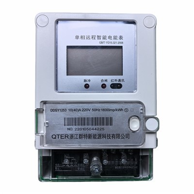
If you’re ready to stop guessing at your energy costs and start using data to cut waste, get in touch with our team to discuss your requirements. We can walk you through our product lineup, help you select the right meter for your site, and answer any questions about how reactive power measurements work for your specific application. No sales jargon, no hidden fees, just accurate, reliable meters backed by years of field testing.
Prepaid Energy Meter REFERENCES
- IEEE Standard for Instrument Transformers – Definitions, Performance Requirements, and Test Specifications, IEEE Std C57.13-2020
- Electrical Measurement, Signal Processing, and Displays, Keyue Smedley, CRC Press, 2004
- Power Quality in Power Systems and Electrical Machines, Ewald F. Fuchs, Mohammad A. S. Masoum, Academic Press, 2015
- NEC Article 314: Electronic Energy Metering Applications, National Electrical Code, 2023
Zhejiang Qunte New Energy Technology Co., Ltd.
As one of the most professional electronic energy meter manufacturers in China, we’re featured by quality products and good price. Please rest assured to buy discount electronic energy meter made in China here from our factory. We also accept customized orders.
Address: No. 56, Fengxi Road, Tang’ao Yu Village, Liushi Town, Yueqing City, Wenzhou City, Zhejiang Province
E-mail: 251951196@qq.com
WebSite: https://www.zjqtmeter.com/
